
-40°C to 120°C
NBR (Nitrile) seal limit
Typical NBR guidance often spans about -40C to 120C; hot or chemical exposure usually pushes review toward FKM-class materials and supplier seal data.
Actuator Assembly RFQ Checker
Screen whether an actuator assembly scope is ready for RFQ or needs a DFM/pilot loop first. The same canonical page covers actuator assembly definition, drawing review, actuator assemblies, actuator assembly process, and actuator assembly and testing intent through one supplied boundary: actuator, interface, magnetic or sensor target, retention method, and validation evidence.
Decision Evidence Review
Evidence review updated 2026-06-27. Use this section to see which definition, testing, material, and source-boundary gaps can change a sourcing decision before you freeze drawings, tooling, or supplier responsibilities.
| Content Gap Found | Decision Risk | Information Added |
|---|---|---|
| Alias intent for actuator assembly process needed a unified answer. | A visitor searching for the assembly process could miss the mechanical datums and curing constraints that make the actuator viable. | Added assembly process mapping to the drawing review and thermal boundaries on this canonical URL. |
| Irreversible demagnetization boundaries and ingress protection standards were lacking. | Buyers might not realize that temperature-induced irreversible flux loss acts as a permanent failure in assembled actuators since remagnetization is impossible post-assembly. Also, IP ratings (IEC 60529) were missing for environmental seal validation. | Added NdFeB grade boundary temperatures (80°C to 230°C) and irreversible loss limits. Included IEC 60529 (IP Ratings) and a separate electrical-safety review boundary. |
| Functional safety and wear mechanisms (FMEDA, SIL) were missing. | Safety-critical applications could improperly rely on basic cycle tests instead of structured Failure Modes, Effects, and Diagnostic Analysis (FMEDA). | Added IEC 61508 boundaries, SIL response time considerations, and NBR/FKM seal temperature limits. |
| Interface standards were named but not bounded. | A buyer could mistake a mounting standard for proof that the actuator assembly is correctly sized. | Added source-by-source boundaries for ISO 5211, ISO 15552, IEC 60068, ASTM B117, and NEMA thermal context. |
| Alias intent for actuator assembly and testing needed a visible answer. | A visitor searching for testing guidance could miss that the canonical actuator assembly page includes both architecture screening and validation evidence. | Added first-screen, navigation, summary, risk, validation, and FAQ language that maps actuator assembly and testing to this single canonical URL. |
| Alias intent for actuator assembly definition needed a first-screen and report-layer answer. | A visitor asking for a definition could miss the supplied-boundary meaning and treat the page as testing-only. | Added visible definition language, a supplied-boundary table, navigation anchor, and FAQ coverage on the canonical actuator assembly page. |
| Material guidance had useful coefficients but weak sourcing context. | Temperature drift, corrosion exposure, and molded target use cases could be over-generalized. | Separated NdFeB, SmCo, ferrite, and bonded magnet tradeoffs and marked supplier-grade data as required before release. |
| The RFQ checker explained risk, but not enough about evidence packages. | Visitors could run the tool without knowing what records are needed to turn a boundary result into a production decision. | Expanded validation gates and scenario rows with measurable pass/fail evidence and fallback paths. |
| No explicit unknown-data policy. | Claims about final life, drift, and field failure rate would be stronger than public evidence supports. | Added visible "to be confirmed" language where public data cannot support a universal conclusion. |
| Alias intent for actuator assembly drawing needed a visible answer. | A visitor looking for an actuator assembly drawing could miss that this canonical page explains the tolerance stack-ups, datums, and interface requirements. | Added drawing review anchors, tolerance stack-up diagrams, and FAQ coverage mapping actuator assembly drawing to this single canonical URL. |
| Drawing GD&T and inspection realities were missing. | Users might design a perfect tolerance stack-up but fail to realize that standard CMM probes deflect near magnets, or that heat-curing adhesives will ruin the magnet. | Added ASME Y14.5 / ISO 1101 datum strategy, non-magnetic CMM styli requirements, and adhesive cure temperature risks. |
-40°C to 120°C
Typical NBR guidance often spans about -40C to 120C; hot or chemical exposure usually pushes review toward FKM-class materials and supplier seal data.
PST set by safety owner
For safety-instrumented functions, response-time allocation must be set in the safety requirements specification; this page does not certify SIL performance.
1.5x-2.5x
Use as early RFQ triage, not final release evidence.
40C
NEMA motor guidance uses 40C as a common ambient reference; above that, allowable temperature rise usually needs derating.
2026
ISO 5211:2026 is listed as published in February 2026 for part-turn valve actuator attachment requirements.
4 gates
Load, travel, thermal, and interface evidence should close before production release.
1 URL
Actuator assembly, actuator assembly definition, actuator assemblies, actuation systems assembly, actuator assembly process, and actuator assembly and testing are answered here.
3 scopes
Define actuator assembly, magnetic sub-assembly, and actuator assembly and testing separately before comparing quotes.
< Tmax
Oven-cure temperatures for epoxies must stay safely below the magnet maximum operating temperature to avoid irreversible loss.
Ruby / Optical
Ferromagnetic probe hardware can bias position checks near strong magnets. Confirm ruby, carbon-fiber, ceramic, or optical inspection details in the quality plan.
80°C - 230°C
Depending on grade (N to AH), NdFeB irreversible demagnetization occurs if limits are exceeded. In assembled actuators, this is a permanent failure.
Magnet thermal limits & safety boundary review
When NdFeB magnets exceed their grade-specific maximum operating temperature (80°C for N grades up to 230°C for AH grades), they suffer irreversible flux loss. While technically recoverable by re-magnetizing, this is practically impossible once the actuator is assembled, making it a permanent field failure. Grade selection must account for peak internal eddy current heating, not just ambient temperature.
Definition boundary table
For RFQ and validation work, actuator assembly means the actuator plus the mechanical interface, magnetic or sensor target, retention method, and driven mechanism assumptions that the supplier is expected to build or verify. The definition must also say what is excluded.
IEC 61508 / SIL boundaries
If the actuator assembly is part of a safety-instrumented function, any SIL claim needs a safety owner, requirements specification, proof-test plan, and Failure Modes, Effects, and Diagnostic Analysis (FMEDA) or equivalent failure-rate evidence. A cycle count alone is not enough.
Seal temperature limits
Dynamic friction in pneumatic or hydraulic seals generates localized heat. Typical NBR (Nitrile) ranges are often quoted around -40°C to 120°C, while FKM-class materials can support hotter or more chemical-resistant packages when the exact compound is verified. Incompatible seals swell or harden, increasing drag and causing the actuator to fail its required response time.
RFQ checklist + validation matrix
The actuator, magnet, bracket, driven mechanism, sensor target, retention method, and test fixture all affect field behavior. A quote based only on magnet grade or actuator frame size is under-specified.
Checker margin logic + risk controls
Hot, vibrating, or corrosive assemblies need more than a room-condition load check because friction, magnet output, adhesive retention, coatings, and spring return can all drift.
Source boundary table
ISO 5211:2026 helps define part-turn valve actuator attachment requirements for industrial valves, but it does not prove your break torque, cycle life, seal friction, fail-state behavior, or magnetic feedback margin.
Validation gate visual
Close force/torque, travel/position, temperature rise, and interface retention before scaling. That is the practical testing layer behind the actuator assembly and testing search intent.
Material temperature tradeoff table
Public magnet-design references commonly show sintered NdFeB Br dropping faster with temperature than SmCo, but exact coefficients, maximum operating temperature, and irreversible-loss limits depend on grade and geometry. That makes supplier grade sheets and sample thermal checks part of sourcing, not a catalog afterthought.
Environmental test boundaries
ASTM B117 is useful for controlled coating comparisons, while IEC 60068 vibration and temperature-change methods frame environmental exposure. None of those methods can be converted into field life without actuator-specific acceptance limits and post-exposure function checks.
Adhesive & Magnet thermal limits
Heat-cure epoxies offer excellent strength and environmental resistance, but baking the assembly too close to the magnet maximum operating temperature or Curie temperature causes irreversible magnetic loss. Always validate the cure profile against the specific NdFeB or SmCo grade sheet.
CMM measurement protocols
Standard steel CMM probes will be attracted to the magnetic sub-assembly, causing deflection, false contact triggers, and position measurement errors. Specify ruby balls, carbon fiber stems, or optical/vision inspection methods on the quality plan.
Drawing GD&T checklist
When applying ASME Y14.5 or ISO 1101 to actuator drawings, the Datum Reference Frame (DRF) should use stable, machined housing surfaces as primary datums rather than brittle or coated magnet edges. This ensures the tolerance stack-up analysis reflects reality and prevents unstable CMM setups.
Actuator Assembly Definition
On this canonical page, actuator assembly definition means the boundary statement that tells engineering, purchasing, and supplier quality what is included, what is excluded, and what evidence closes the risk. That is why the definition, drawing guidance, and testing matrix live on the same URL.
| Definition Scope | Usually Includes | Usually Excludes | Evidence to Request |
|---|---|---|---|
| Actuator assembly | Actuator, bracket or housing interface, driven linkage, magnet or sensor target, retention method, and release-state requirement. | Final machine control logic, certified valve package, or field service-life claim unless those items are named in the RFQ scope. | Supplied-boundary drawing, interface datums, load/travel assumptions, and first-article validation plan. |
| Magnetic actuator sub-assembly | Magnet grade, carrier geometry, air-gap datum, adhesive or mechanical retention, and sensor-output verification. | Complete motor, gearbox, firmware, or safety certification unless the program explicitly includes partner responsibility. | Flux map, position repeatability record, thermal drift check, and post-exposure retention result. |
| Actuator assembly and testing | Architecture screening plus load, travel, thermal, interface, and retention evidence before production release. | Inspection-only offers that do not include measured function after environmental or duty-cycle exposure. | Gate-by-gate test record with remaining uncertainty marked instead of hidden in a pass/fail label. |
Boundary note updated 2026-06-27: public standards can help name interfaces and test methods, but the actuator assembly definition is still program-specific. If the RFQ does not name the supplied boundary, treat any price or validation promise as incomplete.
Actuator Assembly Drawing Review
The alias keyword actuator assembly drawing is answered on this canonical actuator assembly page because the drawing is the control document for the same supplied-boundary decision. Use this review layer to decide whether a drawing can go to RFQ or needs a DFM, tolerance stack-up, or first-article evidence loop first.
Drawing check: the mechanical baseline must connect datum A, air-gap range, axial offset, sensor target, and retention process to inspection evidence. If the drawing only shows envelope geometry, the quote cannot prove actuator assembly validation readiness.
| Drawing Item | Must Show | Decision Risk | RFQ Action |
|---|---|---|---|
| Supplied-boundary view | What the supplier owns: actuator, bracket, driven link, magnetic target, sensor, retention method, and release-state evidence. | Prevents a quote from treating actuator assembly, magnetic sub-assembly, and testing as separate or unowned scopes. | Attach a boundary mark-up or exploded view before requesting pricing. |
| Functional datum scheme | Primary/secondary/tertiary datums tied to machined housing, shaft, flange, or bracket surfaces used in real assembly. | Keeps GD&T aligned with the way the actuator is built, inspected, and loaded. | Ask for a stack-up review before freezing first-article inspection. |
| Magnet-to-sensor air gap | Nominal gap, min/max gap, axial offset, angular tilt, and the measurement method used after assembly. | Small shifts can move the magnetic output outside the usable sensing window. | Request a flux map or sensor-output record with the drawing review. |
| Retention and cure process | Adhesive, press-fit, fastener, overmold, sleeve, or hybrid retention plus cure temperature and inspection record. | A drawing can pass mechanically while the cure profile damages magnet output or the retention path fails vibration. | Require cure profile and pull/retention evidence when heat-cure bonding is used. |
Source review updated 2026-06-27. The standards below are used as interface or test-method anchors only; none of them can prove a finished actuation systems assembly without program-specific measurements.
| Source | Used For | Boundary |
|---|---|---|
| IEC 61508 / IEC 61511 | Functional safety and SIL certification framing | Provides functional-safety framework language. It does not certify this actuator assembly by itself; SIL claims require project safety requirements, proof-test assumptions, diagnostic coverage, and manufacturer-specific failure-rate data. |
| ISO 9001 / ISO 17025 | Assembly process quality and calibration competence (Updated: June 2026) | Does not mandate specific assembly tolerances. It only mandates that you identify equipment, define calibration intervals, and use a verifiable Test Uncertainty Ratio (often 4:1) for torque/alignment tools during the assembly process. |
| ISO 5211:2026 | Industrial valves, part-turn actuator attachments | Official ISO records identify the 2026 edition for industrial valves and part-turn actuator attachments. Use it for pad/interface language, then add measured break torque, running torque, end-stop, fail-state, and feedback checks. |
| ISO 15552:2018 | Pneumatic cylinder bore and mounting interface context | ISO lists the 2018 pneumatic-fluid-power cylinder standard as reviewed and confirmed in 2025. It can help with cylinder interface language, but it does not validate the driven mechanism, magnetic target, bracket stack-up, or duty-cycle thermal behavior. |
| ISO 22153:2020 | Electric valve actuator requirements context | ISO identifies ISO 22153:2020 as general requirements for electric actuators used with industrial valves. Use it for actuator classification and requirement framing, then add program-specific cycle, torque, fail-state, feedback, and environmental acceptance records. |
| NEMA MG 1 public guides | Motor insulation and temperature-rise context | NEMA guide material uses 40C ambient as a key reference and discusses temperature-rise adjustment above 40C. It frames motor thermal review but does not validate the finished actuator assembly. |
| IEC 60068-2-14:2023 | Temperature-change environmental test framing | IEC describes Test N for change of temperature. Use it to frame thermal cycling exposure, then define actuator-specific pass/fail limits for force, travel, sensor output, and retention. |
| IEC 60068-2-6:2007 | Sinusoidal vibration environmental test framing | IEC lists the sinusoidal vibration test method as stable until 2029. Use it when vibration can loosen brackets, shift magnetic targets, or change latch travel; still add fixture resonance, fastener, and adhesive-retention checks. |
| ASTM B117 | Controlled salt-fog corrosion screen | ASTM explicitly warns that salt-spray correlation and extrapolation are not always predictable. Treat B117 as a comparative coating, seal, and post-exposure force screen, not a stand-alone service-life predictor. |
| ISO 9409-1:2004 | Robot mechanical interface reference when the actuator assembly mounts to automation equipment | ISO lists the 2004 edition for manipulating industrial robot mechanical-interface plates. Use it for exchangeable end-effector interface language, not as proof of actuator load, magnetic feedback, gripper force, or collision load cases. |
| Internal pilot records, 2024-2026 | Practical RFQ defaults and risk prompts | Used only for screening prompts and default risk logic. Public evidence is insufficient to claim final life, field failure rate, or universal margin without program-specific test reports. |
| ASME Y14.5-2018 / ISO 1101:2017 | Geometric Dimensioning and Tolerancing (GD&T) for drawing stack-ups | Defines the language for Datum Reference Frames (DRF) and geometric controls. It ensures drawings control concentricity, runout, and profile, but does not guarantee the designer picked the correct functional datums. |
| Adhesive manufacturer guidelines (e.g., Loctite, Permabond) | Magnet bonding and curing kinetics | Supplier datasheets provide shear strength and cure temperature profiles. Treat brand examples as procurement prompts only; the assembler must confirm the exact adhesive, cure profile, and magnet irreversible-loss threshold before release. |
| IEC 60529 | Ingress Protection (IP) ratings for enclosures | Defines the standard for sealing against dust and water (e.g., IP67, IP68). Useful for specifying environmental limits of the housing and seal, but it does not prove dynamic seal friction or life cycle durability under load. |
| Electrical safety standard review | Safety requirements for electric actuators and solenoids | IEC 61010-2-202 was treated as a safety-review prompt during content enhancement, but no stable public IEC product URL is linked here. Confirm the applicable edition through the compliance owner before using it in a customer safety claim. |
Figure 5: ISO 5211 publishes reference torque values for part-turn actuator attachment interfaces. Treat them as interface-screening values, then verify the actual actuator assembly with break torque, running torque, coupling fit, keyway strength, and end-stop load records.
The phrase actuator assemblies can mean a valve pad, pneumatic cylinder package, robot flange, or custom magnetic latch. The RFQ should name the supplied boundary first; otherwise standards, drawings, and test records can refer to different parts of the system.
| Interface Type | Useful Reference | Include in RFQ | Not Proved by Reference |
|---|---|---|---|
| Quarter-turn valve actuator | ISO 5211:2026 | Valve type, stem dimensions, mounting pattern, break torque, running torque, fail position, media temperature, corrosion exposure. | Seal friction over life, actuator torque margin, magnetic feedback drift, spring-return proof, and site-specific corrosion. |
| Pneumatic cylinder package | ISO 15552:2018 | Bore, stroke, pressure, mounting style, guide load, rod/end fitting, cycle rate, sensor target position. | Bracket stack-up, actuator-side shock loads, magnetic switch hysteresis, and application-specific duty-cycle heating. |
| Robot or automation end effector | ISO 9409-1:2004 | Flange pattern, payload, moment load, collision case, cable routing, gripper or latch state, repeatability target. | Actuator internal force-speed curve, magnetic holding force, fixture resonance, and controls integration. |
| Custom magnetic latch or sensor assembly | Program drawing + first article record | Air gap, magnet grade, target material, datum scheme, force or switch threshold, temperature and vibration exposure. | No public standard can prove a custom magnetic circuit by name alone; sample maps and post-exposure checks are required. |
Figure 1: Typical dimensional stack-up of an integrated magnetic feedback target on a rotary/linear actuator shaft. Datum A (shaft centerline) acts as the mechanical baseline. Concentricity runout must be constrained below 0.15mm to avoid air gap changes and sensor noise.
Figure 2: DIN 6885 torque-keyway width fit limits. P9 interference fit is required for continuous modulating service to prevent reversing impacts, whereas Js9 is acceptable for simple on-off valve assemblies.
Figure 3: ISO 15552 piston rod guide runout limit specifications. Control concentricity to prevents rod bending and cylinder seal deterioration under high load cycle applications.
| Check Point / Dimension | Governing Standard | Recommended Value | Failure Risk if Out-of-Spec |
|---|---|---|---|
| Coaxiality of coupling bore to shaft | ASME Y14.5M / ISO 1101 | less than or equal to 0.05 mm runout | Shaft binding, accelerated coupler seal wear, high drag torque. |
| Center axis deviation of sensor magnet | ASME Y14.5M / ISO 1101 | less than or equal to 0.10 mm positioning error | Feedback signal distortion, non-linear output, loss of angle index. |
| Mechanical mounting flange alignment (axial and radial runout) | ISO 5211 / ISO 2768-mH | less than or equal to 0.15 mm radial misalignment | Gasket leakages in valves, side load bearing failures. |
| Keyway tolerances (backlash control) | DIN 6885 / ISO R773 | P9 fit (interference) for Class C/D; Js9 (transition) for Class A/B | Keyway flattening, high hysteresis, impact damage during reversals. |
| Air gap nominal distance and tolerance bounds | Sensor supplier datasheets | Example screen: 1.5 mm to 2.0 mm (+0.3 / -0.2 mm); lock final window by sensor datasheet and flux map | Collision, signal loss, or high noise if the program-specific sensing window is exceeded. |
| Piston rod thread and shoulder runout | ISO 15552 / DIN ISO 965 | 6g thread fit, concentricity less than or equal to 0.15 mm A | Piston rod bending, cylinder end cap bearing failure. |
| Adhesive cure temperature vs magnet grade limit | Adhesive & Magnet supplier datasheets | Cure temp must be safely below the magnet maximum operating temperature and Curie temp | Irreversible loss of magnetic strength during oven-cure cycles. |
| Datum Reference Frame (DRF) stability | ASME Y14.5 / ISO 1101 | Datums must mimic functional assembly and use stable, machined surfaces (not rough magnet edges) | Unrepeatable CMM inspections, false rejections, or functional interference. |
For actuator assemblies, magnet choice is tied to duty cycle, ambient temperature, package size, corrosion exposure, and retention method. Public temperature coefficients are useful for screening, but supplier-grade data and sample testing still decide release.
| Material | Public Data Point | Useful When | Limit / Counterexample |
|---|---|---|---|
| NBR (Nitrile Rubber) Seals | Typical supplier datasheets often cite about -40°C to +120°C; compound-specific | Standard pneumatic and hydraulic actuator seals; excellent oil resistance and cold-weather flexibility. | Will harden and fail at high temperatures. Cannot handle aggressive chemical exposure. |
| FKM (Fluoroelastomer) Seals | Typical supplier datasheets often cite about -20°C to +200°C; compound-specific | High-temperature environments or harsh chemical exposure where long seal life is critical. | Higher cost and poor extreme-cold flexibility compared to NBR. Requires careful specification for low-temp regions. |
| Sintered NdFeB | Br coefficient commonly about -0.11% to -0.12% per C | Highest compact-force option, but hot duty cycles need grade, coating, and irreversible-loss review. | Do not assume room-temperature pull force at elevated actuator temperature. Exceeding the grade limit (80°C to 230°C depending on N to AH grade) causes irreversible demagnetization, which is a permanent failure once assembled. Confirm grade, coating, and maximum operating temperature. |
| SmCo | Br coefficient commonly about -0.03% per C | Better fit for hotter, more stable magnetic output where cost and brittleness are acceptable. | Higher material cost and mechanical fragility can make retention, edge protection, and handling more important. |
| Ferrite | Lower energy product; grade behavior and geometry matter | Useful where cost, corrosion tolerance, or demagnetization resistance matter more than compact force. | Often too bulky for compact actuator packages unless geometry has enough space. |
| Bonded magnets | Public data is resin and filler dependent | Useful for molded sensor targets or complex shapes in lower-force actuator feedback roles. | No reliable public dataset supports a universal strength claim; confirm by supplier grade and molded geometry. |
To be confirmed: there is no reliable public dataset that maps every actuator assembly geometry to final life, drift, and failure rate. Use public material coefficients for screening only, then close the gap with supplier grade sheets and first-article measurements.
Figure 4: Magnetic flux density vs air gap distance decay. The curve is a screening illustration, not a universal sensor threshold; final switching and noise limits must come from the selected sensor, target geometry, magnet grade, and measured flux map.
A 0.1 mm air-gap deviation can materially shift output on compact targets, but the percentage is geometry-dependent. Maintaining a controlled stack-up and measuring the actual response is the release requirement.
| Alignment Parameter | Nominal Design Target | Allowable Deviation Limit | Verification and Measurement Method |
|---|---|---|---|
| Radial Air Gap | 1.5 mm - 2.0 mm | +0.3 mm / -0.2 mm | Go/No-Go pin gauge, 3D CMM coordinate check |
| Axial Offset Shift | 0.0 mm (perfect center alignment) | +/- 0.5 mm | Sensor mapping fixture, laser distance verification |
| Angular Tilt / Misalignment | 0.0 degrees | +/- 2.0 degrees max tilt | Concentricity fixture check, custom magnetic angle scanner |
| Temperature-induced magnetic output shift | Use supplier grade sheet; NdFeB AH, SmCo, and bonded grades have different limits | Program-defined drift and irreversible-loss limit after thermal exposure | Thermal chamber cycle testing, hall sensor voltage telemetry logs |
| Coordinate Measurement (CMM) Probing | No probe or fixture bias during measurement | Confirm ruby, carbon-fiber, ceramic, or optical/vision systems where magnetic attraction can bias readings | Review CMM inspection plan before first article approval |
| Assembly Fastener Torque | Per supplier specification (e.g., 5.0 Nm for M5 Grade 8.8) | Tolerance defined by ISO 9001 traceable procedure (Test Uncertainty Ratio 4:1 required as of June 2026) | Inline transducer monitoring, calibrated torque wrench, breakaway torque FAT (Factory Acceptance Test) |
Use this matrix to decide whether a quote is ready for pilot build or still missing evidence. The goal is not more paperwork; it is to catch the failure path before tooling, fixtures, and annual-volume pricing are locked.
| Gate | Evidence Needed | Decision It Supports | If Evidence Is Missing |
|---|---|---|---|
| Functional Safety (SIL) | Safety requirements, FMEDA or equivalent failure-rate evidence, and proof-test interval definition | Supports a safety-owner review of failure rates, diagnostic coverage, and proof-test assumptions. | If those records are missing, do not claim SIL performance from this checker; treat the assembly as standard commercial hardware until the safety file is closed. |
| Load / torque | Measured pull-in, hold, breakaway, or torque-angle record | Confirms whether the checker margin survives real friction and voltage conditions. | If no measured load exists, keep the result as boundary and run a small pilot before tooling. |
| Travel / feedback | Stroke, end-stop, sensor target, or magnetic output map by fixture | Confirms that air gap, bracket datum, and target eccentricity do not shift switching or position output. | If the datum scheme is missing, freeze drawings only after stack-up review. |
| Thermal | Duty-cycle heat-rise log plus before/after force or travel check | Confirms whether motor heat, magnet temperature coefficient, adhesive limits, or housing creep change output. | If ambient exceeds 40C or duty exceeds 50%, use boundary status until heat-rise data exists. |
| Environment / retention | Vibration, temperature-change, corrosion screen, and post-exposure functional check | Confirms that standards-based exposure did not hide a bracket, coating, seal, or adhesive failure path. | If only salt spray is available, do not claim natural-environment life; mark it as comparative evidence. |
Figure 6: Actuator testing evidence timeline. ISO 22153:2020 is used here as general requirements context for industrial-valve electric actuators; project-specific cycle counts, starts, load windows, heat-rise limits, and pass/fail criteria still need to be written into the RFQ and first-article plan.
Use this checklist when a supplier says testing is included. The record should name the test unit, timing, measured condition, and remaining uncertainty; otherwise the phrase actuator assembly and testing can hide an inspection-only offer.
| Test Unit | When to Run | Record Required | Still Unknown |
|---|---|---|---|
| Component (Magnet/Coil) | Incoming Inspection | Flux Density / Resistance Log | Assembly Alignment |
| Sub-assembly (Actuator) | Post-assembly before housing | Stroke / Force Verification | Environmental Durability |
| Final Unit | Pre-shipment (100%) | End-of-Line Test Report | Long-term Fatigue |
Source note updated 2026-06-27: ISO, IEC, ASTM, and NEMA references are used only for interface language or test-method framing. Public evidence is insufficient to claim universal actuator life, drift, failure rate, or supplier process capability without program-specific measurements.
| Option | Best Fit | Main Risk | Validation Gate |
|---|---|---|---|
| Solenoid assembly | Short stroke, fast actuation, binary on/off behavior | Heat rise and weak holding margin at high duty cycle | Current profile, temperature rise, pull-in/drop-out force |
| Pneumatic actuator assembly | High cycle production automation where compressed air is already available | Air quality, leakage, cushioning, impact load, and sensor switch drift | Pressure/load curve, cycle-speed record, cushion setting, leakage check, sensor repeatability |
| Linear actuator assembly | Controlled stroke, higher load, repeatable travel | Back-drive, screw wear, guide misalignment, speed/load mismatch | Force-speed curve, travel repeatability, duty-cycle thermal log |
| Rotary actuator assembly | Indexing, latch release, flap control, rotary feedback | Angle stop drift, backlash, sensor target eccentricity | Torque-angle trace, end-stop durability, magnetic feedback map |
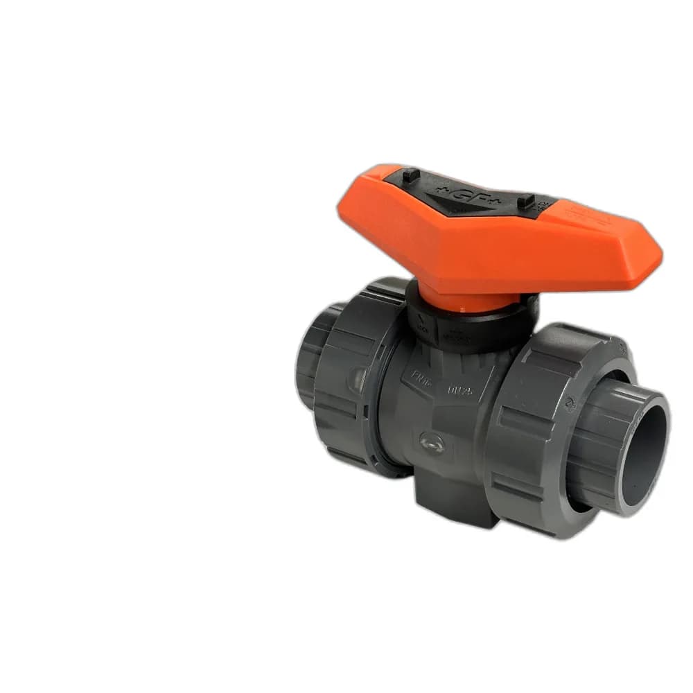
| Valve actuator interface | Quarter-turn valve, damper, or process-control interface | Mounting mismatch, stem torque spike, fail-state ambiguity | ISO 5211 pattern review, break torque, fail-state test |
Trigger: Manual assembly without inline transducer feedback or uncalibrated wrenches.
Mitigation: Under-torquing leads to vibration loosening and leakage; over-torquing causes thread stripping. Use ISO 17025 calibrated tools and Statistical Process Control (SPC) for torque signatures.
Trigger: Chemical incompatibility, particulate ingress, or temperature exceeding NBR/FKM limits.
Mitigation: Verify seal material limits, add ingress protection, and validate dynamic response time after thermal aging.
Trigger: Margin below 1.5x after friction, temperature, and voltage assumptions
Mitigation: Increase frame size, reduce friction, add spring assist, or validate lower-speed operation.
Trigger: Duty cycle above 50% or ambient above 60C
Mitigation: Run heat-rise logging and recheck magnetic output, adhesive retention, and travel force.
Trigger: No common datums between actuator, bracket, valve pad, shaft, or driven mechanism
Mitigation: Add datum scheme, mounting pattern, stack-up review, and pilot travel records.
Trigger: Using ISO/NEMA/IEC references as if they replace application tests
Mitigation: Use standards for language and method framing, then define program-specific acceptance limits.
Trigger: Passing ASTM B117 is used as a direct claim for outdoor or plant-floor lifetime.
Mitigation: State the exposure hours, coating stack, and post-exposure function result; confirm real-service corrosion risk separately.
Trigger: RFQ language alternates between actuator assembly, actuator assemblies, actuation systems assembly, actuator assembly process, and actuator assembly and testing without a shared drawing scope.
Mitigation: Define the supplied boundary: actuator only, actuator plus bracket, magnetic target, sensor package, valve interface, or tested sub-assembly.
Inputs: High-temperature process, fail-close requirement, SIL 3 target, fast response time
Result: FKM-class seal review, spring-return fail-state evidence, safety-owner FMEDA review, and proof-test interval planning required before any SIL claim.
Inputs: 120 N load, 25 mm stroke, 35% duty, vibration exposure
Result: Guided linear actuator assembly with retention and travel records before pilot release.
Inputs: Torque-driven valve pad, spring-return fail mode, corrosive plant area
Result: ISO 5211 interface review plus break-torque and fail-state validation.
Inputs: ISO-style cylinder package, 50 mm stroke, 45% duty, side load from a fixture, magnetic end-position sensing
Result: Confirm mounting interface separately from switch hysteresis, side-load guide wear, and post-vibration sensor repeatability.
Inputs: Short stroke, high cycle speed, clean but high repeatability requirement
Result: Solenoid or rotary latch assembly with sensor target repeatability and heat-rise test.
At minimum, include the supplied boundary, functional datums, magnet or sensor air-gap limits, load or torque path, retention method, environmental assumptions, and the first-article evidence expected from the supplier.
An actuator assembly drawing provides the mechanical baseline (datums, tolerances, air gaps, and runout limits) needed to verify the assembly. This canonical page covers the interface datums and tolerance stack-ups required for a complete drawing review.
An actuator assembly is the supplied motion-control boundary: actuator, mounting interface, driven element, magnetic or sensor target, retention method, and validation evidence. The RFQ should also state what is outside scope, such as firmware, certified valve package, or field service-life claims.
The phrase describes the same buyer problem as actuator assembly: selecting, building, and validating a complete actuation interface. Keeping one URL avoids duplicate intent and gives buyers one action path.
It is the same procurement workflow as actuator assembly: decide the supplied boundary, screen architecture risk, and confirm test evidence before release. Splitting it into a second page would duplicate the same buyer path and weaken the canonical URL.
Yes. Buyers using the plural phrase usually need the same workflow: choose an actuator architecture, define the magnetic or mechanical sub-assembly, check interface risk, and collect validation evidence. This page keeps both phrases on one canonical URL.
No. It is an RFQ screening tool. Final sizing needs measured force or torque, voltage, friction, temperature, travel, and supplier test evidence.
It is useful when position sensing, holding, latching, return-state control, compact packaging, or sealed interface behavior depends on magnetic circuit geometry.
Low margin, high thermal exposure, demanding fail-safe behavior, or missing interface details push the result into boundary status.
No. They help define interfaces and methods. They do not prove your assembly can meet program-specific torque, load, cycle-life, or environmental limits.
It depends on the supplied boundary. ISO 5211 is relevant to part-turn valve actuator attachments, ISO 15552 can frame pneumatic cylinder interfaces, ISO 9409-1 can frame robot mechanical interfaces, and IEC 60068 or ASTM B117 can frame environmental screens. None of them replaces assembly-specific force, travel, heat, retention, and feedback evidence.
ASTM warns that salt-spray correlation and extrapolation are not always predictable. Use it as a controlled comparison for coating or seal options, then state post-exposure function results and confirm real operating exposure separately.
Send load or torque, stroke or angle, speed, duty cycle, environment, voltage/current constraints, drawings, fail-state requirements, and acceptance criteria.
Sometimes. High heat, vibration, or safety-critical release states often need mechanical backup, overmold, sleeve, fastener, or hybrid retention validation.
Consider SmCo when the actuator assembly needs better magnetic stability at elevated temperature and the design can tolerate higher material cost and brittleness. NdFeB remains attractive for compact force, but hot duty cycles need grade-specific irreversible-loss review.
Use force/torque, travel/position, temperature, and interface-retention evidence. A visual pass alone is not enough for an actuator assembly.
Mark the assumption as unconfirmed, run a small pilot or DOE, and use the result to lock the quote and production control plan.
The primary scope is magnetic and mechanical assembly support. Electronics or firmware can be coordinated only when the program scope and partner responsibilities are explicit.
Send the checker inputs with a drawing or sketch. That gives engineering enough context to respond with a validation-oriented RFQ review.
Yes. The page connects architecture screening with practical test gates so buyers can move from concept to supplier evidence without splitting the keyword intent.
The actuator assembly process is covered directly on this canonical page. It includes the tolerance stack-up diagrams, adhesive curing limits, CMM measurement procedures, and validation testing required to build and verify a reliable actuator assembly.
| Metric | Typical Range | Why It Matters |
|---|---|---|
| Force/Torque Safety Margin | Screening target 1.5x-2.5x vs validated peak load | Prevents stall, missed travel, or weak holding when friction, wear, and voltage conditions shift |
| Duty-Cycle Thermal Status | Project-defined; review against winding, magnet, adhesive, and housing limits | Actuator assemblies often fail when heat rise changes magnetic output or retention behavior |
| Position / Air-Gap Repeatability | Project-defined, commonly verified by fixture-based travel or sensor-output records | Small alignment drift can change force, sensor switching, valve travel, or latch release timing |
Before releasing tooling or annual-volume orders, align your supplier review on one measurable acceptance baseline, one practical pilot test method, and one signed risk-closure record. This removes ambiguity during engineering handoff and prevents quote-stage assumptions from leaking into production.
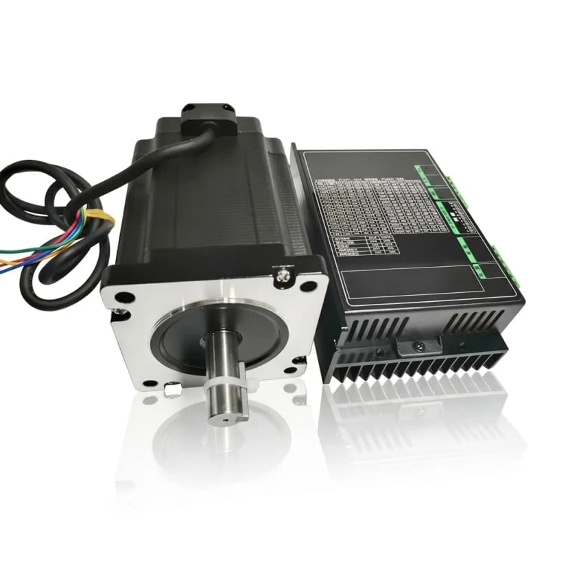
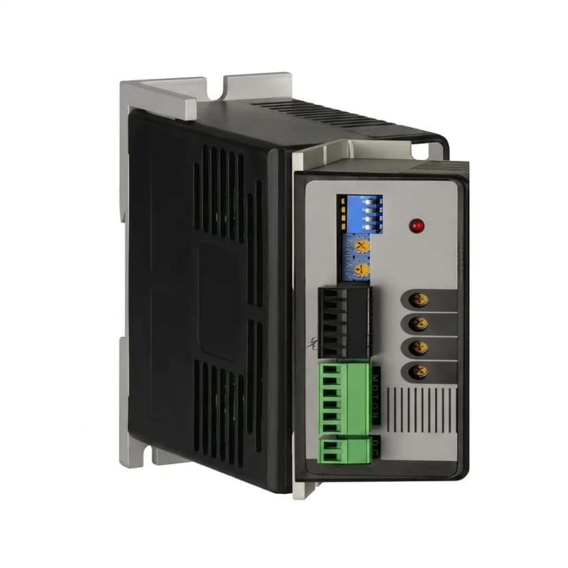

An actuator assembly is defined as a complete, integrated motion-control sub-system (actuator, mounting bracket, driven linkages, position sensors, and targets). Establishing this definition early limits integration issues.
A custom actuator assembly drawing must specify mechanical datum schemes, critical magnet-to-sensor air gaps, force/torque transmission paths, fastening tolerances, and specific surface coatings or encapsulation parameters to prevent field failures.
An actuator assembly drawing is the mechanical baseline for building and testing the system. Merging these intents on a single canonical /products/actuator-assemblies page prevents duplicate page risk and provides a unified resource for engineers.
Yes. The plural phrase actuator assemblies and the singular actuator assembly describe the same buyer intent here, so both are answered on this canonical /products/actuator-assemblies page instead of split into duplicate routes.
For this site, yes. We treat actuation systems assembly as an alias of actuator assembly and keep one canonical URL for the combined actuator, magnetic sub-assembly, and validation workflow.
Yes. Actuator assembly and testing belongs to the same buyer intent as actuator assembly here: define the assembly boundary, screen the architecture, and collect force, travel, thermal, retention, and feedback evidence before production release.
We support magnetic and mechanical sub-assemblies around the actuator interface. Full motor, gearbox, electronics, or certified valve packages depend on the program scope and approved partner stack.
Send the load case, stroke or rotation angle, speed, duty cycle, voltage/current limits, operating environment, drawings, and validation acceptance targets.
Yes. We can compare the magnetic assembly and interface risk for each path, then recommend which samples or tests should be run before tooling lock.